PROJECT 07 – RGB LED
INTRODUCTION
An RGB LED is really three LEDs inside a single device – one red,
one green and one blue.
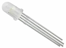
It has four legs (pins). The longest leg
is common to all LEDs inside. Some
models use a common anode (positive) and some use a common cathode (negative)
pin. See the diagram below.
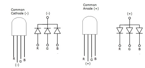
The
legs R,G and B need to be connected to a resistor and
then to either Vcc or ground (the opposite of the
common leg).
The
resistor values should not be the same.
The red LED needs a lower voltage drop across it so the resistance
should be higher than for the other two colours.
For
use with a 5 volt source, the red leg's resistor should be about 300 ohms while
the other two colours should each have a resistor of
about 180 ohms. Of course, you can try
other higher values and will likely have success.
WORK
Connect
an RGB LED to a power source and resistors.
Make sure you are comfortable with how it works.
To
get 4/5, you need to be ready to set the colour to
what Mr. Campeau asks for.
To
get 5/5, you need to use a potentiometer on each LED colour
leg to gradually adjust the colours manually.
This is pretty cool!