PROJECT
06 – RELAYS
INTRODUCTION
A
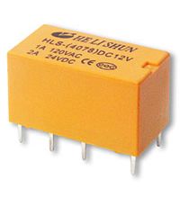
relay is a device that allows one circuit to control another circuit. It allows one circuit to turn on or off the
other circuit – so it's an electrically controlled switch. The general use is to allow a circuit with a
small current to control a circuit with a larger current. Below is a relay that resembles one of the
models that we have in class:
The
controlling circuit is called the primary circuit while the circuit that is
controlled is called the secondary circuit.
For
us, this is useful because devices such as Arduinos can be damaged by high
currents. On the other hand, motors
require higher currents than Arduinos can handle. So, by using a relay, we can control motors
with Arduinos without really connecting the two.
INSIDE A RELAY
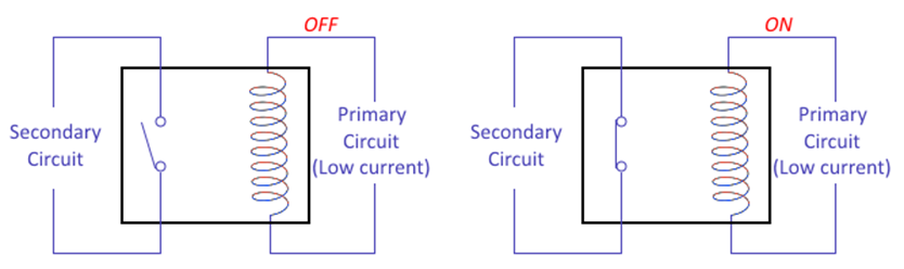
The diagram
below shows how the inside of the relay changes when the primary circuit is
powered ON versus when it is OFF. As you
can see, the switch that closes the secondary circuit changes positions based
on the state of the primary circuit.
RELAYS WITH BOTH NO AND NC
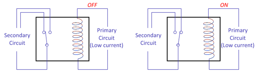
Some relays
connect the secondary circuit's switch to two different pins so that the switch
has one common pin (C) at one end and two pins at the other end: one normally
open (NO) and one normally closed (NC).
DEVICES WITH TWO RELAYS
ON-BOARD
Some relay
devices have two pins for the primary circuit, three pins for the secondary
circuit and another three pins for another secondary circuit.
PINOUT
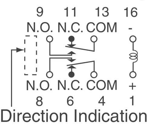
The above
graphic shows the pinout diagram of our relays.
When the coil between pins 1 and 16 is disconnected, the COM pin is
connected to its corresponding NC pin.
When the coil pins are powered, the COM pin is now connected to its
corresponding NO pin.
WORK
Get a relay
from Mr. Campeau. It should have the NO
and NC options on it.
Connect the
primary circuit pins to a power source.
Connect the NC
pin to LED, resistor and a second power source.
Connect the NO
pin to a different LED and resistor and then to the same second power source.
Testing: When the primary circuit is OFF, one LED
should be on. When the primary circuit
is ON, the other LED should be on instead.
Show Mr.
Campeau.