PROJECT 02 – DIODES
OVERVIEW
A
diode is a very simple electronics device that allows current to flow through
it in one direction, but not in the other.
SIMPLE CIRCUITS
A
few circuits for you to try. They will
take only a few minutes and you do not need to show Mr. Campeau.
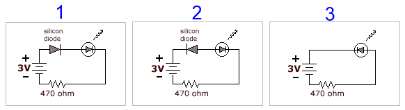
After
you've built these circuits on a breadboard, you'll notice that the LED from
circuit 1 lights up but the LED's from the other circuits
dosen't. Do you know why?
Recall that a diode only lets current flow in 1 direction. In circuit 2, the
diode is placed in the opposite direction from circuit 1. It is not allowing
current to flow through. Remember that LED's are diodes too. In circuit 3, the
LED is placed so that it is opposing current flow so it is not lighting up.
DIODE LOGIC
Diode
logic (DL) allows us to create an AND gate and an OR gate (but no others.)
Diode
logic suffers from voltage degradation (drop) from one stage to the next
because diodes and resistors do consume voltage. This is a major issue and the reason DL isn’t
used inside ICs.
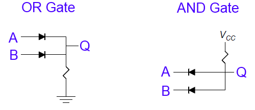
DIODE OR GATE - DISCUSSION
At
first glance, the diode OR gate may seem overly complicated for no reason. One might think that the diodes could
actually be removed and simply replaced my normal wires. However, in the states when one input is 1
and the other is 0, the current would enter via one input and exit via the
other (remember that inputs that are zero are grounded). So the diodes are necessary!
Furthermore,
one may question why the resistor to ground is necessary. After all, if you are simply implementing this
OR gate to light up an LED, then the resistor to ground won’t be
necessary. However, when doing logic, we
have to consider the possibility that there will be other gates beyond Q. And, for these gates to get an ouput of 0 from the OR gate, it needs to be able to connect
whatever is beyond Q to ground – it is the resistor to ground that does this.
You
might also wonder about that resistor to ground and how current flows through
it when Q=1. First off, it does depend
on the resistance value of the resistor. But yes, current will flow through two
branches (one branch with the resistor to ground, and one with whatever is
beyond Q).
DIODE AND GATE –
DISCUSSION
The implementation
of the diode AND gate is much easier to understand. If either input provides access to ground
(zero), then the current entering from Vcc will all
exit via that input.
Interestingly,
when both inputs provide a 1, that is simply forcing
the current from Vcc to go to Q. We usually imagine that the current entering
the inputs is the same as the current exiting the output but that is not the
case here.
To
explain why we need a resistor, let’s consider the situation where either input
(or both) has a zero. So current will
flow from Vcc directly to ground. Without a load (resistor), this would be
shorting out our circuit.
PROJECT EXPECTATIONS
You
should create all five circuits on this page.
Be sure you understand how to orient diodes.
You
only need to show one circuit to Mr. Campeau.
You decide between the Diode OR gate or the
Diode AND gate.