COMPONENT INFORMATION – POTENTIOMETERS
INTRODUCTION
A potentiometer, also commonly called a pot, is an electronic device with a
resistance that can be changed by the turning of a dial or the sliding of a
lever. Depending on how it is connected
to the circuits, it can be used either as a voltage divider or as a variable
resistor. More on this later.
POTS IN THE REAL WORLD
Pots
are best known for being the volume dial on your radio. They are also used in dimmer switches in your
home.
IMAGES
Here
are a few images of common pots:
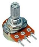
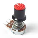
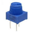
And a few pots that are
breadboard friendly:

HOW POTS WORK
Understanding
how a pot works is pretty simple.
|
|
For
the pot animation on the left, the black material resists the flow of current
through it. The
left pin is connected to one end of the black material while the right pin is
connected to the other end of that same material. Because the distance between these two pins
is always the same, the resistance between the two is always the same. The
middle pin is connected through the rotary dial to the moving half
circle. The half circle makes contact
with the black material at its top peak (near the black dot). So the amount of black material between the
middle pin and the side pins changes as one turns the dial. This means that the resistance between the
middle pin and the side pins changes as one turns the dial. When
the dial is turned counter-clockwise to the end, the center pin is in contact
with the left pin meaning there is no resistance. However, it also means that the center pin
is as far as possible from the right pin, meaning they experience the maximum
resistance. |

|
|
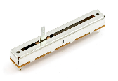
The
idea with a slider pot is exactly the same.
As the central level which is connected to the central pin moves, its
distance from the other two pins changes. |
CIRCUIT DIAGRAM SYMBOLS
There
are two different symbols that are used for pots. Thankfully they are fairly easy to
understand.
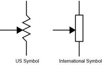
Please note that the arrow
does not specify direction of current.
SPECIFICATIONS
The
most important information is the maximum
resistance of the potentiometer. This
can be easily measured using an ohm-meter by connection both prongs of the
meter to the outside legs of the pot.
Otherwise,
you are most likely interested in its form and whether or not it can be
conveniently used with a breadboard.
COMMON USES
There
are two common approaches to using a potentiometer – as a variable resistor and as a voltage
divider.
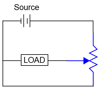
VARIABLE RESISTOR
We
can use a pot as a variable resistor simply by leaving one of the outside legs
open (floating). The pot now only makes
use of two legs (like normal resistors) and the resistance between these two
varies with the dial turning. Here is a
diagram of a pot used as a variable resistor:
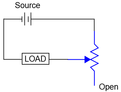
VOLTAGE DIVIDER
We
can also use pot as a voltage divider.
For a load that has a resistance that is considerably higher than the
pot’s max resistance, turning the pot’s dial can provide the load with a voltage
ranging from 0V up to nearly100% of the source’s voltage. Here’s the circuit (similar):
ANALYSIS - VARIABLE
RESISTOR vs VOLTAGE DIVIDER
|
Circuit
Type |
Load
Resistance |
Pot
– Max Resistance |
R1 |
R2 |
V1 |
V2 |
VL |
|
Variable
Resistor |
10K |
1K |
500 |
500 |
1/21st
of source |
N/A |
20/21st
of source |
|
Voltage
Divider |
10K |
1K |
500 |
500 |
~50%
of the source |
~50%
of the source |
~50%
of the source |
Uncertain Issue: Mr.
Campeau questions if the above voltage divider would see most of the current go
through the branch that has no load.
Efficiency issue?
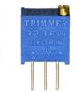
TRIMPOTS
Potentiometers
that are designed for breadboards tend to have a dial that requires a
screwdriver to turn them. These pots are
made more to be “set it and forget it” than to me used to change the
circuit. They are designed as trimmers
(of voltage) that can be set once. So
they are called trimpots. We will use these in class because they are
so convenient to use with breadboards.