LESSON NOTE
INTRO TO MULTIMETERS
A multimeter is a device that allows you to measure
different characteristics such as voltage, current and resistance in circuits
and devices. It is a combination of a
voltmeter and ammeter and an ohmmeter.
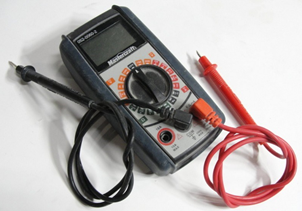
Below is an image of the most common model of multimeter
that we have in class. While it is
simple, it is both effective and inexpensive making it accessible to
everybody.
PARTS OF A MULTIMETER
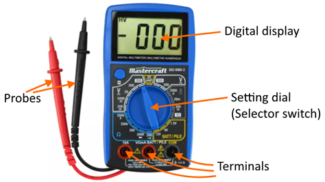
Most multimeters have similar parts. The digital display gives you your
reading. The setting dial allows you
to specify the type of measurement you are wanting to make. The terminals allow you to connect the
probes to the multimeter. And the probes allow you to connect the multimeter to the circuit or device that you are testing.
MULTIMETER’S
POWER
Before
using your multimeter, check if it turns on. Some multimeters
do not have an auto-off switch.
Forgetting them on will kill the battery inside it. Please remember to turn off your multimeter when you are done using it.
PROBES
The black probe should always be connected to the black terminal (common).
The red probe should be connected in one of the red terminals. There is usually one terminal for voltage,
ohms and low currents and another terminal for larger currents.
SETTING
THE DIAL
You must
set the dial in order to measure a specific characteristic. The common options on simple multimeters are:
- DC voltage (symbol: straight lines above V)
- AC voltage (symbol: wavy line above V)
- Ohms (symbol: Omega)
- DC current (symbol: straight lines above A)
- AC current (symbol: wavy lines above A)
RANGES
You will
notice that some multimeters have ranges for each
setting. For example, under DC
voltage, a multimeter might have the following
setting options:
- 200 mV
- 2000 mV
- 20 V
- 200 V
- 1000 V
The value
of the setting is the maximum value that can be read on that setting. If you see a reading of 1, it means that
you are exceeding that value.
For example, if your multimeter is set to 20 V on
DC voltage and the actual voltage of the device is 40 V, your reading will
show 1 as you are reading above the 20 V maximum. The solution is simply to move the dial
over to the 200 V setting to get a good reading.
WARNING
It is important to set the dial correctly and connect the probes of the multimeters correctly to devices/circuits that we are
measuring. Not doing so could be
dangerous and could cause damage to the multimeter.
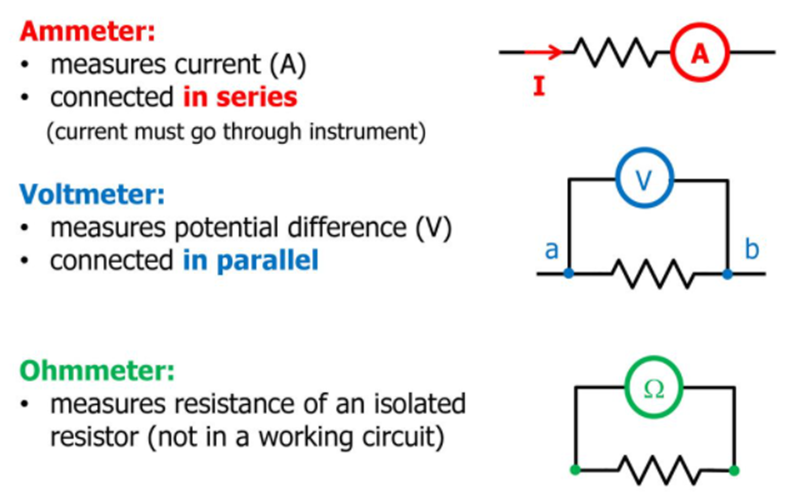
SYMBOLS FOR VOLTMETER,
AMMETER & OHMMETER
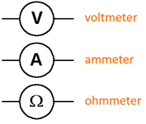
The multimeter is generally used as a voltmeter, an ammeter
or an ohmmeter. Each has its own
symbol to use in circuit diagrams.
<UP TO
HERE. REST NEEDS TO BE ORGANIZED.>
MEASUREMENT
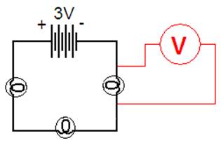
MEASURING VOLTAGE
TOOL:
To measure voltage, we use a voltmeter.
METHOD:
Place one end on one side of a source or load and the other end on the other
side to get the voltage drop.
ADVANTAGE:
We do not need to disconnect the circuit to measure the voltage drop.
DISADVANTAGE:
We need to have access to several points in the circuit to measure all the
different voltage drops throughout.
EXAMPLES
|
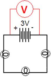
To
measure the voltage drop across the battery.
|
|
|
To
measure the voltage drop across the light bulb.
|
|
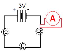
MEASURING CURRENT
TOOL:
To measure current, we use an ammeter.
METHOD:
You must disconnect the circuit and place the ammeter in such a way that it
becomes part of the circuit path.
ADVANTAGE:
We can calculate the current for the entire circuit by having access to just
one section.
DISADVANTAGE:
We need to disconnect the circuit to do this.
EXAMPLE
|
In simple
circuits, you can place the ammeter anywhere in the circuit because the
current does not change in different locations.
|
|
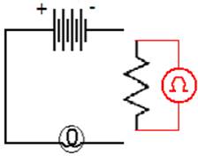
MEASURING RESISTANCE
TOOL: To measure resistance, we
use an ohmmeter.
METHOD:
You must disconnect the material (load) from the circuit and connect the
ohmmeter to each side of the load.
Some more advanced ohmmeter provide four
leads to better test for resistance.
EXAMPLES
|
This will
measure the resistance in the resistor.
|
|
RESISTOR STRIPES
Most
resistors have a pattern of colored stripes to indicate
resistance.
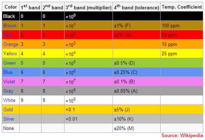
Here is what each stripe does:
- The last stripe is gold or
silver. This gives the precision
of the resistor. It also allows
you to know which stripe is the first stripe (the one at the other
end).
- The first stripe gives you the
first number of the resistance. (Brown is 1, Red is 2, …)
- The second stripe gives you
the second number of the resistance. (Brown is 1, Red is 2, …)
- The third stripe gives you the
multiplier by which you must multiply the first two numbers.
EXAMPLE
Here
is the resistance of a resistor that has the following stripes: red, brown,
orange, gold.
Digit
#1 = 2 (red stripe)
Digit #2 = 1 (brown stripe)
Multiplier
= times 1000 (orange stripe)
Precision
= +/- 5% (gold stripe)
Therefore,
the resistance is 21 x 1000 = 21000 Ohms.
SUMMARY OF MULTIMETER
USE
Image
source: https://slideplayer.com/slide/12275638/
|