|
DESCRIPTION
LINK INSTRUCTIONS NOTE: You should have completed the first activity with
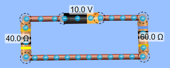
this software before doing this activity. CIRCUIT 1 - SERIES
CIRCUIT INSTRUCTIONS
A)
Use an ammeter to determine the
current in the circuit. Write your
answer down. B)
Add another ammeter elsewhere in the
circuit. Is the current the same or
different? Write your answer down. C)
Using the battery’s voltage and the
measured current, use Ohm’s Law to determine the resistance in the
circuit. Write your answer down. D)
Analyze the circuit to see if your
answer from B seems to make sense with your understanding of resistance in
series circuits. Write your answer
down. E)
Use a voltmeter to determine the V1 (voltage
drop over the 40 ohm resistor R1). Write your answer down. F)
Use a voltmeter to determine the V2 (voltage
drop over the 60 ohm resistor R2). Write your answer down. G)
How do your answers in D and E
compare to the voltage of the battery?
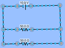
Write your answer down. CIRCUIT 2 – PARALLEL
CIRCUIT INSTRUCTIONS H)
Use a voltmeter to determine the
voltage drop over each resistor. Write
your answer down. I)
Try changing the resistances to
different values. Does the voltage
drop change? Write you answer down. Return the resistances to 50 ohms. J)
Use an ammeter near the battery to
determine the current leaving the battery.
Write your answer down. K)
With the voltage of the battery and
the current reading from the previous step, use Ohm’s Law to calculate the
total resistance for the circuit.
Write your answer down. L)
Consider the circuit and the total
resistance you calculated in the previous step. Does the value match with your
understanding of resistance in parallel circuits? Write your answer down. M)
Now setup two more ammeters – one in
each branch. What is the current in
each branch? Write your answer down. N)
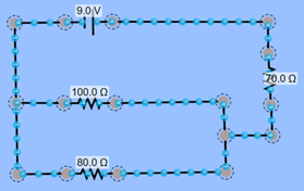
Change the resistances. Try 70 ohms and 30 ohms. How does the current change? Write your answer down. CIRCUIT 3 – COMBINATION
CIRCUIT INSTRUCTIONS O)
Use an ammeter to determine the
current leaving the battery. Write
your answer down. P)
With the battery’s voltage and your
current reading from the previous step, use Ohm’s Law to determine the total
resistance in the circuit. Write you
answer down. Q)
Now calculate the total resistance
using resistance equations. First,
calculate the resistance in the parallel section. Then, calculate the total resistance in the
circuit. Write your answer down. R)
Do your values of resistance in P and
Q match? Write your answer down. S)
Use a voltmeter on each resistor to
determine their voltage drop. Write
your answers down. T)
What relationship (equation) can you
see between the total voltage and R1 and R3? Write your answer down. U)
What relationship can you see between
the VT and R2 and R3? Write your answer down. Save your work to share with your teacher. You will get instructions on how to submit. |