|
DIGITAL DESIGN REVIEW SOLUTIONS ARE AT
THE BOTTOM QUESTION 0 Start off by briefly looking through the Digital Design A
Review to make sure you are comfortable will all concepts.
A)
True or false?
An LED connected to the output of circuit is usually connected such
that the LED is on when the circuit outputs a 1. B)
True or false?
It is possible to make an LED that is connected to the output of the
circuit to be on when the output value is 0 and off when the output value is 1. C)
When the output of a gate is returned back as an
input, this is called a ___________ ____________. D)
A ______________ circuit is a circuit whose output is
entirely based on the current input values.
It contains to feedback loops. E)
A ______________ circuit is a circuit that contains a
feedback loop. The value of its output
is based on both the value of the inputs and the past value of the output. F)
The small amount of time for the output of a gate to
reflect the gate’s inputs is called the ____________ ____________. G)
A ___________ ___________ is when the output of a
circuit is dependent on the propagation of the input signals through the
circuit. H)
A(n) __________ ___________ is a fundamental memory
circuit with two inputs S and R. I)
Input S stands for _______________ and input R stands
for ______________ in an S-R latch. J)
In an S-R latch, when both S & R are
______________, the value of Q latches and stays the same as it was in the
previous input state. K)
A ___________ S-R latch is a standard S-R latch that
includes an input E which stands for ____________. L)
In a Gated S-R Latch, when E is _____, then the
outputs are locked in even when S and R are
changed. M) A
_____ _____________ is a Gated S-R Latch with an extra NOT gate that is
connected so the S and R inputs never get the same value. N)
A ______________ is a periodic electrical signal that
alternates regularly between a low state and a high state. O)
The _____ ______________ IC can be used to create a
clock generator. P)
A circuit that has an output that is only changed at
the moment that a clock input changes is an _________ __________ circuit. Q)
A circuit that doesn’t use a clock and can have its
output change at anytime is a ___________
___________ circuit. R)
A ___________ ____________ is a circuit that is a
latch that uses a clock and a pulse detector instead of the E input. These circuits are edge-triggered. S)
Latches and flip flops are very similar but
___________ do not use clocks and are therefore not edge-triggered. T)
True or false?
Edge-triggered circuits a synchronous circuits
while level-triggered circuits are asynchronous. QUESTION 2 a)
If input A is switched back and forth between 0 and
1, what will happen to Q?
b)
If input A is switched back and forth between 0 and
1, what will happen to Q?
QUESTION 3 Draw the following SR latch on the breadboard below. Make sure to label your R and S inputs and
both your outputs. No LEDs needed
here.
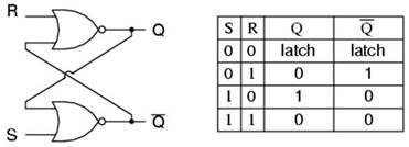
QUESTION 4 An SR latch can be made using NOR gates (like above) or NAND
gates. Research the NAND gate
implementation and draw it on the breadboard below.
QUESTION 5 Draw a gated SR latch on the breadboard.
QUESTION 6 Draw a D latch on the breadboard.
SOLUTIONS QUESTION 1 b-true (by flipping the LED around and connecting the wire
to 5V instead of 0V) c-feedback loop d-combinational e-sequential f-propagation delay g-race condition h-S-R latch i-set, reset j-zero k-gated, Enable l-zero m-D Latch n-clock o-555 timer p-edge-triggered q-level-triggered r-flip flop s-latches t-true QUESTION 2 a-The output Q will get stuck at 0. b-The output Q will get stuck at 1. QUESTIONS 3-6 See Mr. Campeau if you have questions. |