|
The D-type
flip-flop has its own symbol, of course.
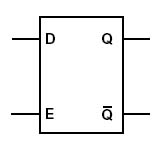
This flip-flop is
sometimes called a transparent latch, because while Enable is high, the
data outputs follow the data input. Because the latch holds the data
forever while the enable input is low, it can be used to store information,
for example, in a computer memory. Lots of latches plus a big decoder
equals one computer memory.
If two data-type
latches are connected as below, the result is an edge-triggered latch:
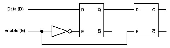
In this
configuration, two transparent D-type latches are connected in tandem. The
enable input, when low, causes the first flip-flop to be in the transparent
state, and the second flip-flop to be locked. When Enable goes high, the
second flip flop becomes transparent first, then after a brief delay the
first flip-flop becomes locked. The output of the second flip-flop will
show the locked output of the first. Even though the second latch is in its
transparent state, the data on the output will not change, because the
first latch is locked. When enable goes low again, the second flip-flop
becomes locked first, then the first becomes transparent. The data output
will remain unchanging, because now the second flip-flop is locked. The
only time new data can be stored in the circuit, is during the brief moment
when the enable input goes from low to high. This transition is referred to
as a rising clock edge, and so this tandem latch configuration is called a
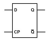
rising edge triggered latch. The two flip-flops and inverter can be
enclosed by a box, and represented by a single symbol. The Enable input of
the transparent latch is replaced by the clock pulse (CP) input. The
edge-triggered latch is one of the central circuits in computer design.
|