|
COMBINATION CIRCUIT PROJECT
AIRCRAFT LANDING GEAR
PROJECT
You will create the circuit for an aircraft landing gear system.
SPECIFICATION
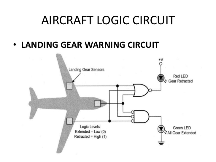
Consider the aircraft landing gear warning circuit below.
FULL DISCLAIMER
Please note that this
circuit was not exactly taken from the Boeing website so the next time you are
repairing an airplane, don't blame me if this circuit doesn't match the one
on your plane.
BRIEF
EXPLANATION
The airplane has three landing gear sensors.
Each sensor is responsible for checking if its wheel is extended (0)
or retracted (1). Pilots are given two
LED lights to show the state of the landing gear.
NOTES
Notice that the Red LED is connected backwards to our normal approach. In
this situation, it will be on when the NOR gate outputs a 0.
The circles before the AND represent NOT gates.
WORK
Start by figuring out how the circuit logically works.
You must be able to answer:
·
When
will the green light be on?
·
When
will the red one be on?
·
When
will they both be off?
·
When
will they both be on?
Once you are
comfortable with the circuit, build it on a breadboard. Use both a red and green LED.
Show your teacher.
|