|
TASK – MULTIPLEXER (MUX) TASK DESCRIPTION A multiplexer is a device which allows one of a number of inputs
to be routed to a single output. Here is a 4-1 multiplexer. We specify which input gets routed by using
the control inputs.
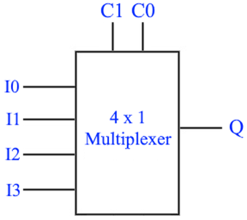
Above, you see a block diagram of a 4x1 multiplexer. In this task, you will create the circuit for a multiplexer. THEORY – ABOUT MULTIPLEXERS Consider
the 4 x 1 multiplexer in the block diagram above. The inputs I0 to I3 are different input
lines that come from different sources.
The multiplexer allows us to route one of those four input lines to
Q. To determine which one, we specify
the value of the control inputs C1 and C0.
·
when C1 and C0 are 00, then Q = I0. ·
when C1 and C0 are 01, then Q = I1. ·
when C1 and C0 are 10, then Q = I2. ·
when C1 and C0 are 11, then Q = I3. So, a
multiplexer is simply a way of selecting which of the four inputs is
connected to Q.
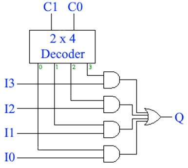
THEORY – CREATING A MULTIPLEXER We can
implement a multiplexer using a decoder, AND gates and OR gates.
The key is
to start with a decoder. The control
inputs for the MUX are the decoder’s inputs.
Remember that only one of the decoder’s outputs will ever be 1. So, if the
line represented by the green 1 is 1, then it will be the input line I1 that
is connected to Q. Students often find
it challenging to understand this.
Remember that all other lines leaving the decoder are zero which get ANDed with the other input lines to give a zero. So, the OR gate will OR three zeros from
the inactive lines and the last value from the active line. THEORY – USES FOR MULTIPLEXERS Multiplexers are useful in
many situations. For example, in a CPU, data being written to memory might
come from one of a number of sources - from a register, from the result of a
calculation, etc - so a multiplexer would be used to select
data from the appropriate source. TASK First,
create a 4-input OR gate. This
requires that you create an integrated circuit. Third,
create a multiplexer: ·
Create
a 4x1 multiplexer for a max mark of 90%. (This will get you 100%
in 2021.) ·
Create
a 8x1 multiplexer for a max mark of 100%. Once created, try the following input combinations for a 4x1 Mux: ·
Set C1 and C0 to 00. Then try toggling the input lines I0 to
I3. Which one changes the light bulb? ·
Set C1 and C0 to 01. Again, toggle the input lines. Which one changes the light bulb? ·
Set C1 and C0 to 10. Again, toggle the input lines. Which one changes the light bulb? ·
Set C1 and C0 to 11. Again, toggle the input lines. Which one changes the light bulb? If you created an 8x1 Mux, do similarly to figure out when a
specific input line change the light bulb. TO SUBMIT A screen capture of you mux. Try researching a demultiplexer. Fun stuff!!! J |