|
TASK – IDENTITY COMPARATOR TASK DESCRIPTION An identity comparator is a digital circuit that compares two
numbers and outputs a 1 if they are both the same or a 0 if they are
different. Such circuits are used
regularly in computer systems. In this circuit, we will look at how to create such a circuit to
compare two 2-bit numbers. THEORY
Let’s consider comparing two 1-bit numbers to start. So, A and B are the two inputs.
We want the output to be 1 if A equals B and
0 otherwise. So the truth table would be:
So this is the XNOR gate. PART 2 – MULTI-BIT NUMBERS Each bit in a multi-bit number is its own input into a circuit. So, if we are creating a circuit that works with two 2-bit numbers,
we will have 4 inputs in total. The notation used for a 2-bit number A is usually A1A0
where A1 and A0 are the individual bits. So, if A is the number 10, then A1
is 1 and A0 is 0. For a 2-bit number B, we use the same system B1B0
representing each bit. If we wanted to represent an 8-bit number X, we would have to use
eight inputs X7X6X5X4X3X2X1X0. But we won’t do this here. (Imagine 64-bit numbers like today’s
computers! Yikes!) PART 3 – 2-BIT COMPARATOR So we have four inputs: A1A0 and B1B0 And we have the one output.
We will call it Q. It is true
if the number A is the same as number B.
In other words, Q is 1 when A1 equals B1 and A0
equals B0. So our truth table is:
Analyzing the truth table to come up with a solution would be
challenging – at least for our skill level at this point. Thankfully, we can resolve this by using a little bit of reasoning
instead. We know that the only way we want a 1 for the output is if A1
equals B1 and A0 equals B0. And we know that checking if two numbers are equal is simply an XNOR
gate. So, we get the equation: (A1 XNOR B1) AND (A0 XNOR B0)
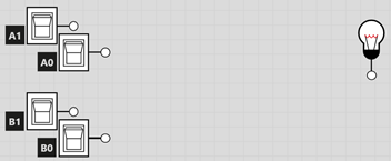
= Q TASK Create a 2-bit number comparator circuit and test it. You are encouraged to setup your input like this:
Test your circuit to make sure the light only goes on with both
numbers are the same.
TO SUBMIT Two screen captures of your circuit. One of the captures has the output light
on. The other has it off. Try making a comparator for two 3-bit
numbers. So you have six inputs and
one output. |