|
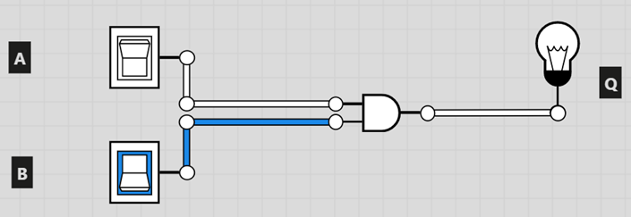
TASK – YOUR FIRST LOGIC GATE TASK DESCRIPTION In this task, you will create a simple circuit with an AND logic
gate. You will also learn how to
create a truth table (logic table) by toggling the inputs and noting the
resulting output. TASK
·
And gate ·
Light bulb ·
2 Toggle switch ·
3 Labels
B) We can now create a truth table by toggling through the different input combinations.
ii) Toggle the switches so A=0 and B=1. Write down the corresponding value of Q. iii) Toggle the switches so A=1 and B=0. Write down the corresponding value of Q. iv) Toggle the switches so A=1 and B=1. Write down the corresponding value of Q. Of course, this simply allowed us the verify the truth table for an
AND gate. In the next tasks, you will
be able to use this process to find the truth table of more advanced
circuits. A screen capture of your diagram. (No need to submit the truth table.) |