|
SOLUTIONS FOR DIGITAL
DESIGN A QUIZ REVIEW #1
But this would also be acceptable:
#2
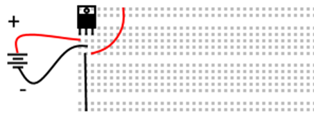
#3 Note that in the image below, one can make the case
that I should have made the shorter leg as the negative leg. (But that’s too much work to change on the
computer.)
#4 NAND – 7400 OR
– 7432 #5 <ASK MR. CAMPEAU IF YOU NEED HELP> #6 <ASK MR. CAMPEAU IF YOU NEED HELP> #7 Note that you do NOT need to know the equivalent
circuit. This would be provided to
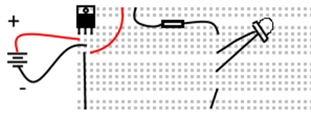
you. <ASK MR. CAMPEAU IF YOU NEED HELP> #8 -Not powered or not grounded #9 Breadboard allow for very easy connections to be
made between devices. Breadboards also
keep the different components steady and organized. Imagine trying to connect everything using
alligator clips! Yikes! Every project would end up as a massive
pile of “stuff”. #10 A pinout is a diagram that provides us with the
functionality of each pin of an IC. <See Mr. Campeau if you need help providing an
example.> Pinouts can easily be found on the internet. Use Google!
The manufacturer of the component also provides a pinout on the site. #12 Truth table A B Co S Circuits: <See Mr. Campeau ifyou
need help drawing the above circuits on the breadboard.> #13 <This question requires that you know the
equivalent circuit for XNOR. This will
not be asked on the test. Though it is
certainly reasonable to do as review.> <Ask Mr Campeau if you
need help.> #14 <Ask Mr. Campeau if you need help.> Note that you should know what a decoder is and
should be able to recreate a circuit diagram for it. This is a fair question for the test. However, it would be very messy to mark for
me. #15 a-F #16 a-decoder #17 For a multiplexer, the value of A & B determine which input line is connected to the output. If AB are 00, the input 00 is connected to the output. If AB are 01, then input 01 is connected to the output. And so on… #18 AB is 10 so input line 10 (C2) is connected to the output. Since C2 has a value of 1, the output will have a value of 1. |