|
MINI LESSON 6 – EXAMPLE OF CONNECTING AN INTEGRATED CIRCUIT CONNECTING AN
INTEGRATED CIRCUIT
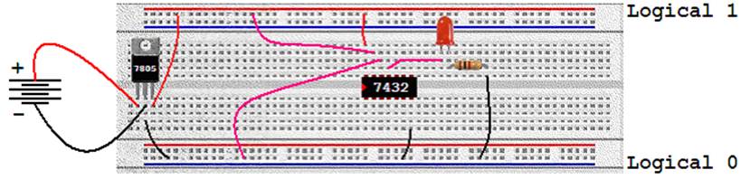
Below is an example of how to use an integrated circuit. The example shows how to connect a voltage
regulator, how to place and power the IC, how to connect the inputs and
outputs of the IC and how to use and LED to demonstrate the value of the
output. Problem
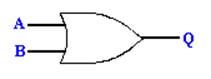
Create the following circuit.
Use LEDs to show values of the inputs and outputs.
Solution
· In
the TTL chip family, chip 7432 holds four OR gates. · This
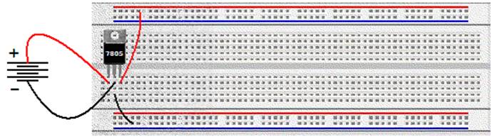
will require us to use a 5 volt regulator. We start by connecting that.
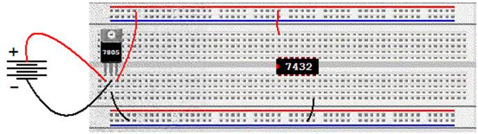
· We
then place the chip and power it (after consulting the pinout if needed).
· We
decide which gate on the chip that we want to use. (The chip has four gates on it.)
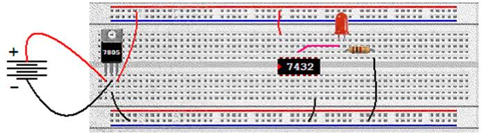
· To
show the value of the output Q, we will connect that output to an LED (and
resistor). The other side is then
connected to ground.
· We
can now test the gate by adding wires from the inputs to either logical 1 or
logical 0. The diagram shows one wire
connected to 1 and one wire connected to 0.
· In
the case above, the LED should be on because one of the two inputs is 1. · Note
that the two wires that are used to provide input to the gate are left long
in this case to make it easier to switch back and forth from 0 to 1. |