|
MINI LESSON 5 – INTEGRATED CIRCUITS “REAL” LOGIC GATES
·
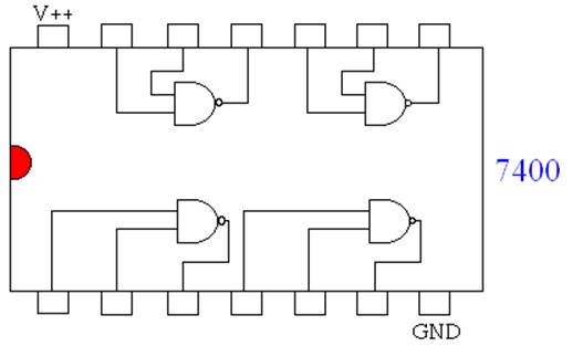
Simple logic gates are created
as small integrated circuit chips that usually contain several gates. Here is an image of such a chip:
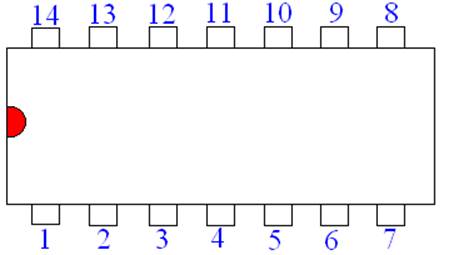
CHIP PINOUTS
·
One can orient the chip based on
the half circle (done in red) on the end of all chips. ·
Pins are numbered 1 to 14
(depending on the amount of pins) in the counter-clockwise direction starting
at the half circle. See below.
·
One aspect that is not
considered in the previous circuit diagrams is the fact that the gates
themselves need to be powered. Two
pins are used for this. The last pin
on the first side of the chip is usually GND and the last pin on the other
side is usually V++. ·
The 7400 ICs are designed to
function with a 5V power supply. COMMON GATE NUMBERS ·
Here is a list of common gate
numbers:
USING IC CIRCUITS
|