PROJECT 09 – 7-SEGMENT DISPLAY
OVERVIEW
You probably use 7-segment displays every day.
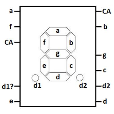
PINOUT
NOTES:
- The
d1 pin doesn’t seem to work.
- CA
= Common Anode (positive). So this
chip uses a common positive pin for all LEDs.
- You
can connect either CA pin to logical 1 and that will be the positive for
each LED.
- Each
LED (segment) has its own negative pin that has to be connect to GRND if
you wish for that LED to be ON.
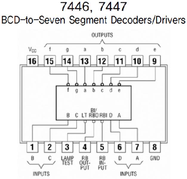
Notes:
- By grounding
pin #3 (lamp test), it will turn on all the LEDs in the display
(essentially showing 8). This is an
easy way to test the display.
- The inputs
represent a binary number with bits DCBA.
So the value 8 is 1000 and 3 is 0011. Notice that D is the most significant
bit and A is the least significant bit.
TASK
Create the circuit that uses the 7447 IC to drive a 7-segment display. You will have to show your teacher a few
specific numbers. For example, here is
the type of request that you will get: “Show me number 6”.