PROJECT 08 – THE FULL ADDER CHIP
OVERVIEW
There is actually a full adder implemented on an IC chip. Sorry, I know I should probably have told you
that before you endured the pain and suffering of the previous project.
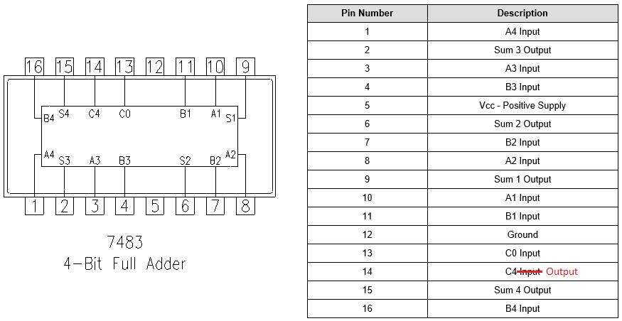
It is on the chip 7483. It is a
4-bit full adder (so it adds two 4-bit numbers together).
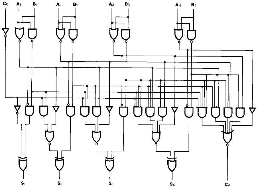
CIRCUIT DIAGRAM
Here is the crazy circuit diagram.
And you thought the 1-bit full adder was challenging?
PINOUT
TRUTH TABLE
Ready to create the truth table? The
good news is that you do not have to go through the circuit as you can quickly
do addition in your head to know the result associated for specific
inputs. The bad news is that there are 9
inputs, so there are 29 = 512 rows in the truth table. Yikes…
Maybe we’ll skip this step. J
Here are the first few lines of the truth table that might help you
understand the inputs and outputs a little better.
|
Inputs |
Outputs |
||||||||||||
|
A4 |
A3 |
A2 |
A1 |
B4 |
B3 |
B2 |
B1 |
CO |
C4 |
S4 |
S3 |
S2 |
S1 |
|
0 |
0 |
0 |
0 |
0 |
0 |
0 |
0 |
0 |
0 |
0 |
0 |
0 |
0 |
|
0 |
0 |
0 |
0 |
0 |
0 |
0 |
0 |
1 |
0 |
0 |
0 |
0 |
1 |
|
0 |
0 |
0 |
0 |
0 |
0 |
0 |
1 |
0 |
0 |
0 |
0 |
0 |
1 |
|
0 |
0 |
0 |
0 |
0 |
0 |
0 |
1 |
1 |
0 |
0 |
0 |
1 |
0 |
|
… |
|
|
|
|
|
|
|
|
|
|
|
|
|
TASK
Make it work! You need a whopping
nine inputs and five outputs. The key will be to remain organized. It is probably best to have your inputs each on
their own rail in order so that you can see what you are inputting.