PROJECT 05 –
HALF ADDER CIRCUIT
OVERVIEW
In
this circuit, you will create a half adder circuit. Essentially, a half-adder is a circuit that
adds two single bits (A and B) and gives off a two bit answer (00, 01 or 10).
This project will force you to use multiple ICs to create your circuit.
THEORY
We want a circuit that will do the
following:
0
+ 0 = 00
0
+ 1 = 01
1
+ 0 = 01
1
+ 1 = 10
To
do this, we need to consider each output bit separately one from another. Instead of calling them Q1 and Q2, we will
call them C and S to represent Carry and Sum.
This
gives us the following truth table:
A B C S
0 0 0 0
0 1 0 1
1 0 0 1
1 1 1 0
But it might be easier to look at this as two separate truth tables for each
output.
a)
The truth table for S:
A B S
0 0 0
0 1 1
1 0 1
1 1 0
The
above truth table is that of the XOR gate.
b)
The truth table for C:
A B C
0 0 0
0 1 0
1 0 0
1 1 1
The
above truth table is that of the AND gate.
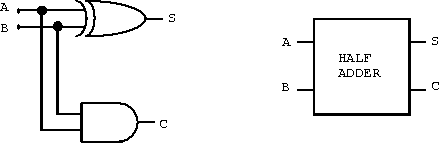
Therefore,
a half adder is created using an XOR gate and an AND gate. Below is the logic diagram and a block
diagram for a half adder.
TASK
Using a
7408 TTL IC (AND gates) and a 7486 TTL IC (XOR gates), you will create your own
half adder. You will need to use 4 LEDs
to show the value of the 2 inputs and the 2 outputs.
You are
expected to place the LEDs in such a way that the LEDs are in order.