PROJECT 03 –
THE NOT GATE
OVERVIEW
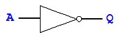
In
this circuit, you will connect a NOT gate.
We take time to examine a NOT gate because it has a different chip
pinout than the other basic gates (due to it having only one input).
BEFORE STARTING
Be
sure a resistor is placed in series with the LED.
Be
sure to use a 5V voltage regulator.
If
the LED doesn’t light up, it might be connected backwards.
PART 1 of 1
Create the following circuit. Be sure to use a voltage regulator.
Use
an LED to show the value of the input and another LED to show the value of the
output.