PROJECT 02 –
YOUR FIRST LOGIC GATE
OVERVIEW
In
this circuit, you will connect your first logic gate and demonstrate how it
works.
BEFORE STARTING
Be
sure a resistor is placed in series with the LED.
Be
sure to use a 5V voltage regulator.
If
the LED doesn’t light up, it might be connected backwards.
Be sure that you can read the numbers on your IC.
Check out the resource section on the index page for the pinouts of the ICs
that we use.
PART 1
Create the following circuit. You will use a 7408 TTL chip. It requires that you use a voltage
regulator. Have an LED show whether the
output is 0 or 1.
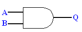
You will have to show your circuit
to your teacher. You will have to show
what the output Q is for all possible values of A and B.
PART 2 (TIME PERMITTING)
Only do the following if you
have the time.
After
you have tested your circuit and you are satisfied it works, add LEDs to show
that values of the inputs. The LEDs must
be setup in parallel with the logic gate so that the voltage drop across the
LED doesn’t affect the input’s value.
Ask
your teacher if you are uncertain.
When
completed, show your work to your teacher.
You will get marks for the neatness of your circuit.