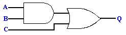
LESSON 02 – LOGIC GATES (AND, OR & NOT)


LESSON NOTE

INTRO TO LOGIC GATES (AND, OR, NOT)


  • Boolean logic is used in electronic circuits.  Two inputs meet at a logic gate and one output leaves the gate. 

  • The inputs are on or off (or 1 or 0).  The output is on or off. 

  •  Symbols for each gate:


/WhatIs/images/and.gif (220 bytes)      AND gate


/WhatIs/images/or.gif (224 bytes)     OR gate


/WhatIs/images/not.gif (244 bytes)      NOT gate (inverter)


  • Example – Draw a diagram of two inputs entering an AND gate.  One input is on and the other is off.  Show the output.


  • Letters are often used to denote inputs and outputs.

  • Example - The diagram below can also be written algebraically like this:  A or B = Q


  • We can now create more advanced logic devices by combining more than one logic gate.  Here are a few examples:


  • Example 1: Create the diagram that represents the following equation: (A and B) or C = Q


  • Example 2: Create the truth table for the above diagram. 


A

B

C

Q

0

0

0

0

0

0

1

1

0

1

0

0

0

1

1

1

1

0

0

0

1

0

1

1

1

1

0

1

1

1

1

1


Note: To create a logic table for more advanced logic devices, we simply list all inputs (and outputs) and then consider the result for every possibility.


  • Example 3: Create the diagram that represents the following equation: not(A or B) = Q


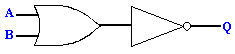
  • Example 4: Create the logic table for the above diagram. 


A

B

Q

0

0

1

0

1

0

1

0

0

1

1

0