|
LESSON 09 – READING
DIGITAL PINS
INTRO In this lesson, we will
learn how to read if a digital pin is high or low. INPUT PIN To read a pin, it needs to
be an INPUT pin. We designate the pin
as INPUT by using the pinMode() function. Here is an example of
making pin #10 an input pin: pinMode(10, INPUT); Note that we do not write
to INPUT pins. They are used for
reading. READING A VALUE To read if a pin is HIGH
or LOW, we use the digitalRead() function.
We do have to specify the pin’s number. Here is an example of
reading pin #8’s value: int value = digitalRead(8); Notice that we are storing
the result of digitalRead(8) into a variable called value. We do this so that we can store and later
use the reading. POSSIBLE VALUES The digitalRead() command
gives either a 0 or a 1. The 0
represents a LOW state and the 1 represents a HIGH state. In programming, instead of
saying that a command gives a certain value, we say that it returns a certain value. NO FLOATING PINS If you try to read from a
floating pin, you will get seemingly random results. The value of the read will switch back and
forth between 0 and 1 with no predictablity.
So we should never allow for a pin to be floating when we are using it
to read. PULL-UP & PULL-DOWN
RESISTORS In digital design, we (almost)
always want a circuit to have either a state of 0 or a state of 1. We almost never want to leave a circuit
open (or floating). Switches that
either open or close a circuit unfortunately create the undesired floating
state. The solution is to use a
pull-up or pull-down resistor along with such switches to assure that the
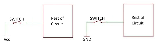
circuit is always 0 or 1. The two circuit drawing
below show two different scenarios where a switch could leave a circuit in a
floating state.
On
the left, when the switch is closed, the circuit gets a HIGH state
inputted. When the switch is open, it
gets a floating (unpredictable) state.
It would be better for the circuit to get a LOW state instead. Similarly,
in the above image on the right, the circuit gets a LOW state when the switch
is closed but a floating state when its open. It would be better for the circuit to get a
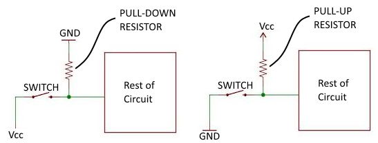
HIGH state when the switch is open. The
images below show how we can add a resistor to the circuits from above to
either pull-up the floating state to a HIGH state or pull-down the floating
state to a LOW state.
The
resistor’s resistance has to be high enough so that when the switch is
closed, most of the current will ignore that branch with the resistor in
it. In other words, when the switch is
closed, the added pulling branch with the resistor doesn’t really affect
anything. When
the switch is open however, the pulling branch provides the circuit either
with a LOW state or a HIGH state (instead of a floating state). |
|
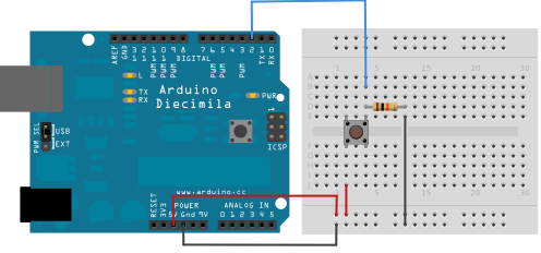
TRY THIS… PRACTICE PROGRAM/CIRCUIT 9.1 A-CIRCUIT Create the following
circuit.
B-DISCUSSION Analyze the circuit to
make sure you understand the explanation below: When the switch is open,
pin #2 is connected to GROUND (via a pull-down resitor). So pin #2 is low. When the switch is closed,
pin #2 is now connected to 5V. So it
is high. C-CODE Write the code that will
continuously read the digital value of pin #2 and output whether it is high
or low to the serial monitor. You
should add a delay of 500 milliseconds between checks. D-TEST YOUR PROGRAM Test your program. You should see the output change when the
button gets pressed. |