|
LOGIC.LY CIRCUITS 1 Go to the free online demo for Logic.ly to create the following circuits. For each circuit, you will
be asked to do a screen capture and then to upload the image to Google
Classroom. TASK 1 –
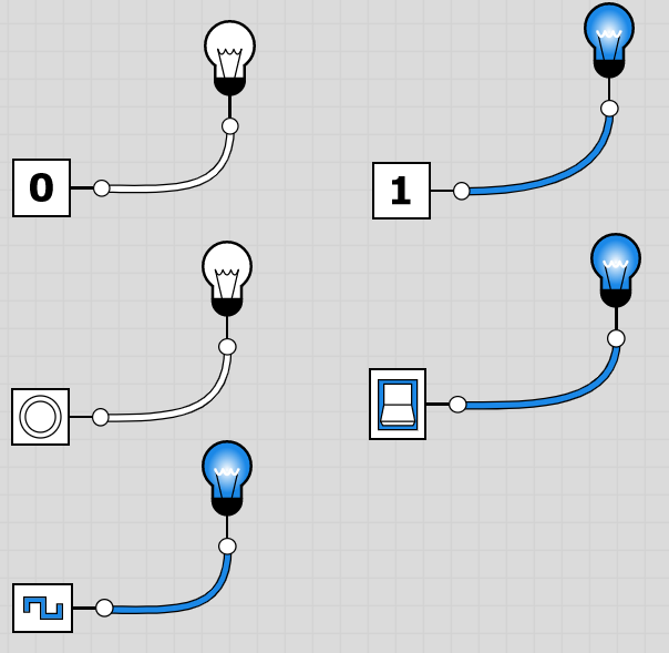
BASIC CIRCUITS Create the following
circuits. Test and analyze each of the
power sources to understand how they work and what they do.
To Submit
To Submit A screen capture or
document with your three truth tables.
Name your file task2b.png (or some other file extension.)
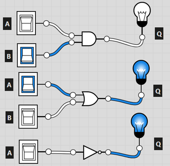
a) Create a circuit like in Part 2 for a NOR gate. b) Create a circuit like in Part 2 for a NAND gate. c) Create a circuit like in Part 2 for an XOR gate. d) Create a circuit like in Part 2 for an XNOR gate. e) Associate each circuit above with its proper truth table below.
To Submit A screen capture of your four circuits. Name your file task3.png. Your answers to the association task (Example: a=table 3, b=table 4, c=table 2, d=table 1). Name this file task3b.png. TASK 4 –
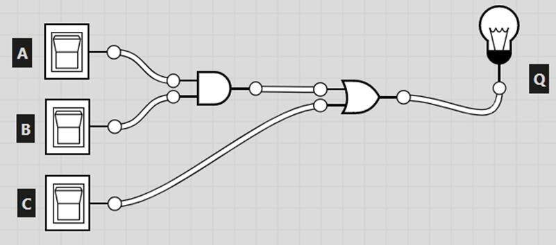
THREE INPUTS Notice the circuit below has three inputs A, B and C. Recreate it in logic.ly and then create the truth table for it. The truth table is started for you below.
Note that the truth table for a circuit needs to include all possible combinations of the inputs. Because there are 3 inputs in this circuit, our truth table will have 8 rows (instead of 4).
To Submit A screen capture of your circuit in a file starting with task4. A screen capture or document of your truth table (will filename starting with task4b). |