ARDUINO 10
CONTENT Please refer
to the grade 11 course for information and details relating to Arduino. PROGRAMS & CIRCUITS Task #1 (Program only) Write a
program that will display HELLO WORLD to screen. Make sure you have selected the proper port
in the Tools menu. Also, you will need
to open the Serial Monitor tool. Task #2 (Program only) Write a
program that will display HELLO WORLD to screen repeatedly. Include a delay between each display. Write a
program that will display HELLO WORLD repeatedly along with the number of
times that it has been displayed. You
will make use of variables for this. Task #4 (Circuit only) Use an
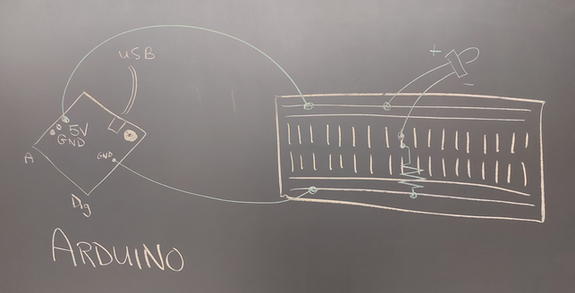
Arduino as the power source to light up an LED. No program is required to do this. See the sketch below.
Task #5 (Circuit & Program)
<TEACHER VERIFIED> Connect the
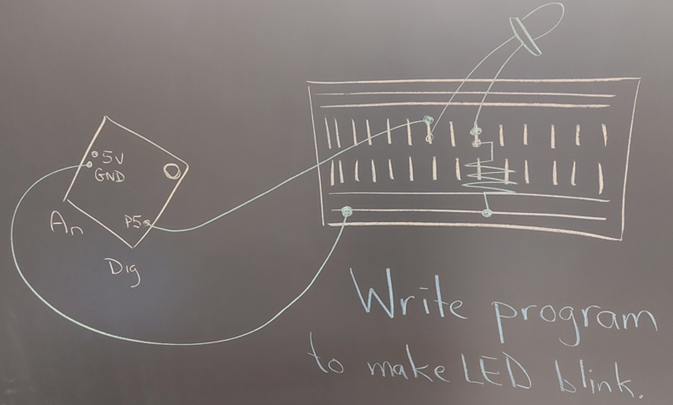
circuit and write the program that will make an LED blink on and off. In the sketch
below, we have opted to use digital pin #5 to connect to the positive side of
the LED. Using programming, we will
have to make pin #5 alternate between a HIGH state and a LOW state to make
the LED turn on and off.
Task #6 (Circuit & Program)
<TEACHER VERIFIED> Using a similar
setup as above, connect the circuit and write the program that will make two
LEDs blink. However, you must meet the
following conditions: ·
When
one LED is on, the other is off. ·
There
is always one LED that is on and one that is off. Task #7 (Circuit & Program)
<TEACHER VERIFIED> Still using a
similar setup as above, connect the circuit and write the program that will
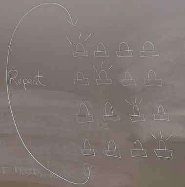
make four LEDs each get their turn to be on for one second. This should repeat indefinitely. See the diagram below.
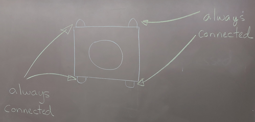
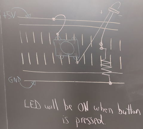
Task #8 (Circuit only) Create the
following circuit that will simply make a button turn on/off an LED. The +5V and GND rails should be connected
to the corresponding pins on the Arduino.
No program required.
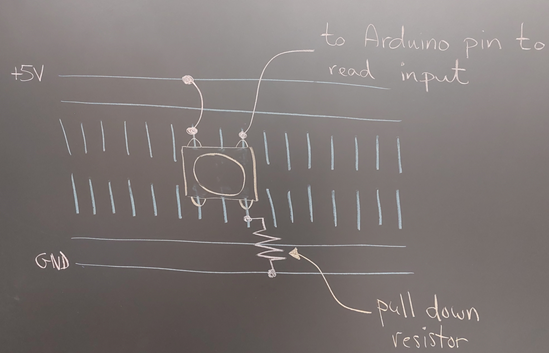
Task #9 (Circuit & Program) Create the
circuit and write the program that will check if a button is pressed or
not. Every second, it should output
either PRESSED or UNPRESSED depending on the state of the button.
Task #10 (Circuit & Program) Alter your
program from above to count the number of times the button has been
clicked. Output the total. Task #11 (Circuit & Program) You will use
a button and an RGB LED. Everytime the button is pressed, it will change the mode
of the LED and display a different colour. Diagram coming?
|