|
|
|
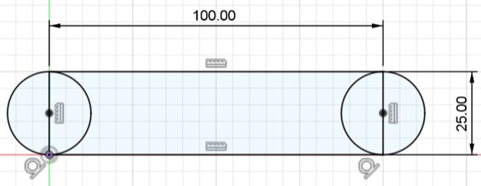
STEP 1 – START THE SKETCH
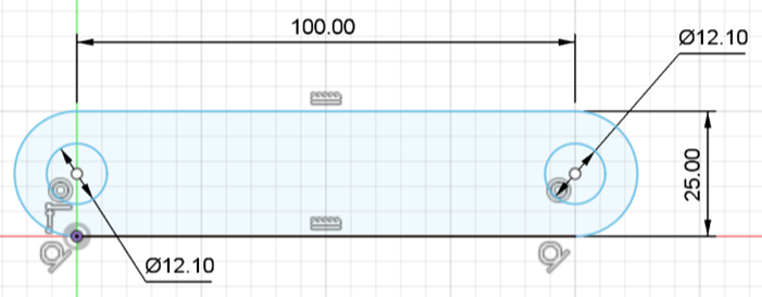
STEP 2 – CONTINUE THE SKETCH
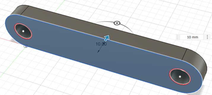
STEP 3 – EXTRUDE (BY 10)
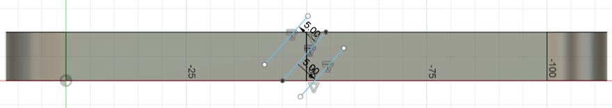
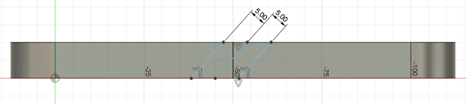
STEP 4 – CREATE A SKETCH ON
THE EDGE OF THE LINK a) Start by creating a vertical line in the middle of the face. b) Create a 45 degrees line that goes through the midpoint of the previous line. c) Use offset (by 5) to create a line on each side of the previous line.
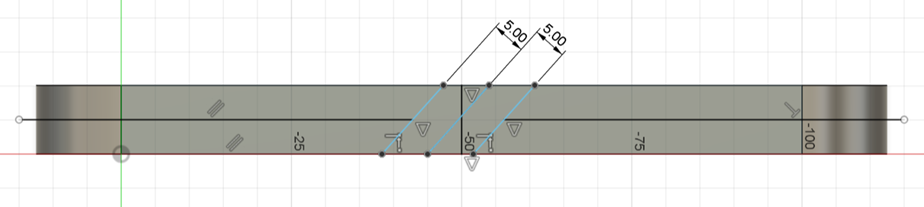
STEP 5 – CONTINUE WITH THE
SKETCH d) Use extend and trim to get to the sketch below.
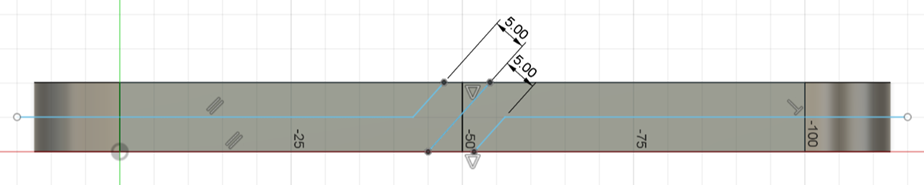
STEP 6 – CONTINUE WITH THE
SKETCH e) Add the two horizontal lines.
STEP 7 – COMPLETE THE SKETCH f) Trim the diagonals. g) Finish the sketch.
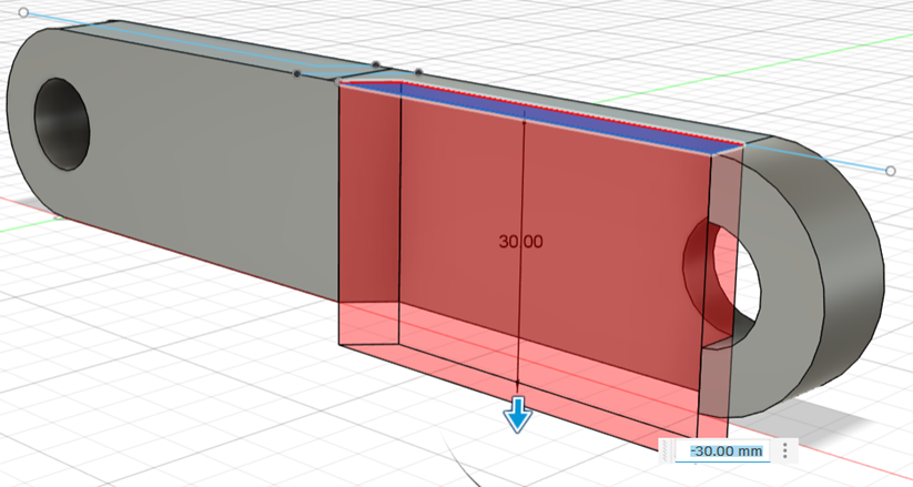
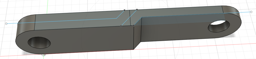
STEP 8 – EXTRUDE a) Extrude the side as shown.
STEP 9 – MORE EXTRUDING b) Extrude away the rest of the excess around the hole. This may take a few different extrudes.
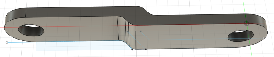
STEP 10 – COMPLETE EXTRUDING c) Do the same to the other side.
STEP 11 – FILLET a) Apply fillet (radius of 5) on four edges.
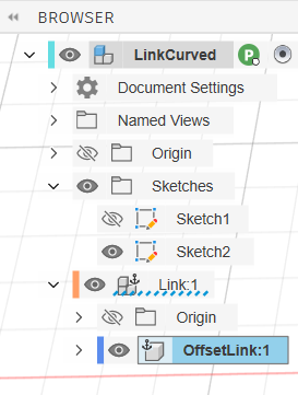
STEP 12 – COMPONENT a) In
the Browser, right-click on the body and choose Create Components From Bodies. b) Right-click on the body and rename it to OffsetLink.
|