|
Orthographic
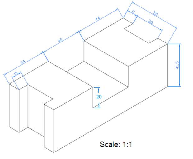
Drawing – Control Bearing NOTE: You are
not to reproduce the drawing below.
You need to create the orthographic drawing of it. The Drawing
STEP BY STEP STEP 1 – DIMENSIONS
STEP 2 – THE VIEWS
Imagine bounding rectangles for each view (see below).
STEP 4 – RECTANGLES IN
AUTOCAD In AutoCad, draw each rectangle to represent your views. In the example, notice that the front view
is 128 by 41.5. The top view is 128 by
50. And the right side view is 50 by
41.5. I decided to leave a gap of 15
between the rectangles.
STEP 5 – THE DRAWING In the example, I am starting with the top view.
I then work on the front view.
I now erase the temporary lines between the views.
I can now do the Right Side View.
I can use measurements from the drawing or I can extend lines from the
Front View.
We can actually also extend lines from the Top View to the Right Side
View (and vice versa) by using a 45 degree diagonal line that starts at the top
right of the Front View (like below).
And now I extend the lines that take a 90 degree turn when they hit the
diagonal line. With these temporary lines, I can now tell where the features on the Top
View appear on the Right Side View.
I can now complete the Right Side View.
And now I remove the temporary lines.
I can also trim the parts of the initial rectangles that are no longer
needed.
Done! |