Unity Guide Part 2B
Advanced Blender
by Drake Smith
The purpose of this guide is to build upon Mr. Killingbeck’s Blender guide and allow you to create fully fleshed out 3D models for your projects using some of the advanced geometry, sculpting, and texturing tools in Blender. This is not a necessary tutorial if you wish to use very basic assets or ones made by others for your Unity project- but where’s the fun in that?
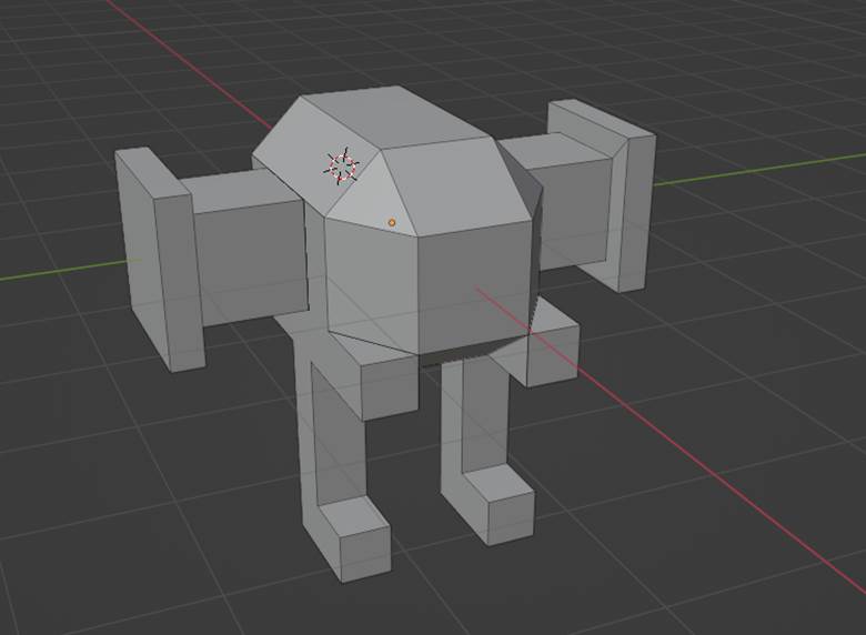
First, open blender, then the “discount ty fighter” model from the first Blender guide. Make sure that you are in Modeling mode at the top of the screen.
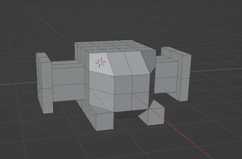 This is truly one of the 3D models of all time.
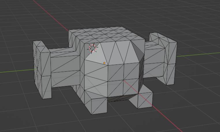
Let’s start by turning this model’s boring squares into the second coolest shape, the triangle. There are various reasons you would want to do this, but the main one that I encounter is that shapes with more than 4 sides cannot be subdivided. First make sure that you are selecting faces with the Selection Type Bar in the top left of the viewport, select the entire object using A, And then right click anywhere to bring up the Face Context Menu. Select Triangulate Faces from the menu.
Your model should now look like this. In this case, Mr. Killingbeck left some funky geometry in his model, And the triangulation happened to fix it. Hooray!
It’s time to make this model really round now, because as I learned from the Pepsi breathtaking design strategy document, circles create an aestheticism that is universally accepted to be in balance and harmony. We’ll remove the top left faces of the ty fighter body first.
Select the top left faces of the body, like this.
Don’t forget the back!
Now, with these faces selected, right click anywhere and select Delete Faces from the Face Context Menu.
Whoops! Looks like the model has a hole in it now! This is terrible aestheticism!
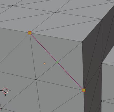
No worries. We can fix this by creating a new face - a lesson I learned from the world’s best plastic surgeon. Select vertex selection mode in the Selection Type Bar and select the 4 vertices on the perimeter of the hole, like this:
Then press F with these vertices selected to create a new face. Make sure the face is smiling. Voila! Good as new!
Let’s forget about this whole face deletion incident.
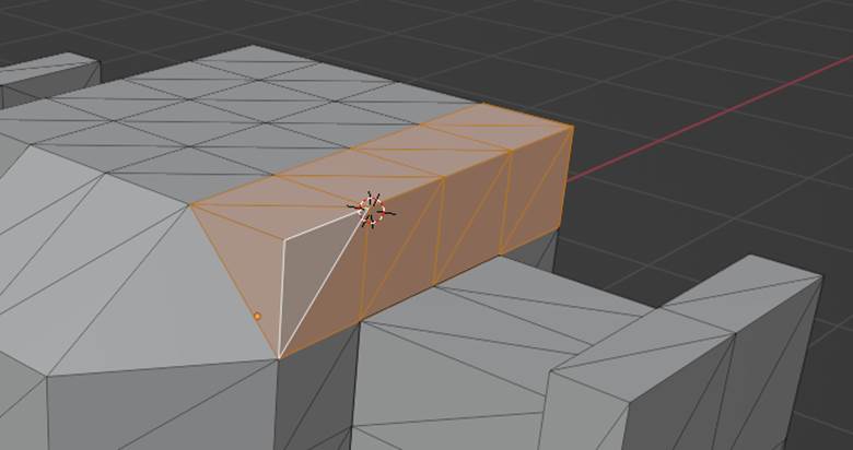
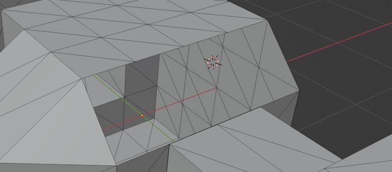
Now, we will round the other side of the body. Let’s try to select the top right faces of the body just as we did the left, and…
Small problem! The triangles at the back are divided the wrong way for taking off the edge like we did on the other side.
Do not fret, there is an easy fix to this issue. Go to the GENUSAR™ on the left side of the screen and select the knife tool.

Remember to only cut away from yourself when using the knife!
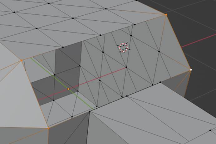
Now, with the knife tool selected, cut a line across the back faces like such simply by clicking one vertice and then another:
Press enter and you have successfully cut these polygons in twain. Now, you may select the faces so that they can be removed like on the other side.
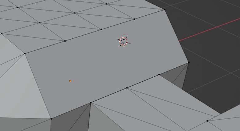
Once again, pull up the Face Context Menu by right clicking, but this time, choose Dissolve Faces. This removes the faces without creating a large hole in the model!
This is how your model should look at this point. Very round… Relatively.
Now, this might seem strange, but one thing that I always felt this model was lacking was a good pair of legs. how should this thing locomote without any?
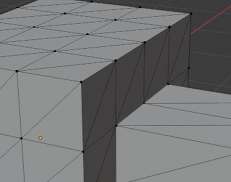
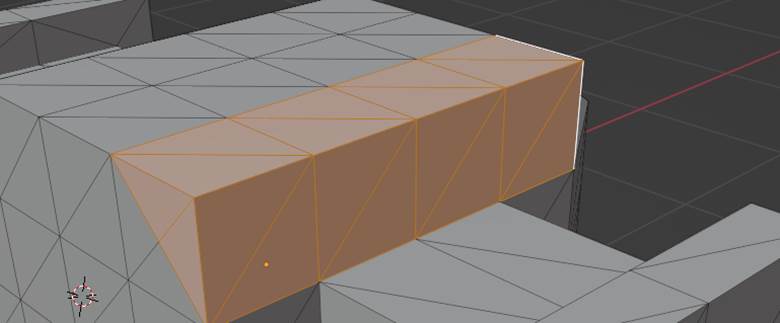
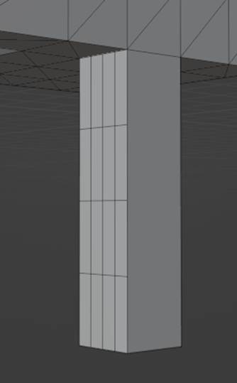
Select these polygons on the bottom of the model and extrude them by any amount you want. Really, any amount. Because of the revolutionary geometrical design of this model, any length will be beautiful. Don’t believe me? Try it for yourself!

Splendid.
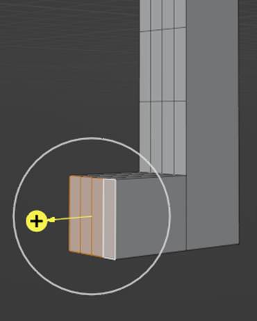
Make sure to also subdivide the front of the leg:
And extrude a foot out of the side, for balance - both aesthetically and literally.
Now, you may be thinking, how will I recreate this leg on the other side when I don’t even remember what its length is? You won’t, because fortunately Blender has a symmetry tool!
If you look at the top of the screen above the viewport, you will see that you are currently in the Modeling mode. For now, we will be switching to Sculpting mode instead.
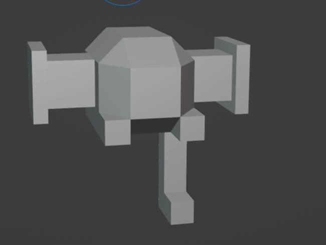
Once you enter the sculpting mode, your model should look smooth. Isn’t that amazing?
Anyways, navigate to the Active Tool and Workspace settings on the right side of the screen…
![]()
Then, navigate to the Symmetry tab. In this tab you will see options for mirroring and some other functions but what interests us here is Symmetrize. First, select a direction (for me, the correct direction is -Y to +Y, but for you this may be different), then simply click on the Symmetrize button. If you did this correctly, the ty fighter should have 2 legs. If you did it incorrectly, the model might be mirrored about a different axis to the intended one. No worries! Just undo this action and try again with a different direction.
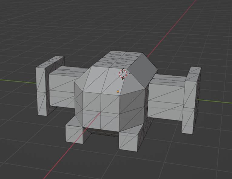
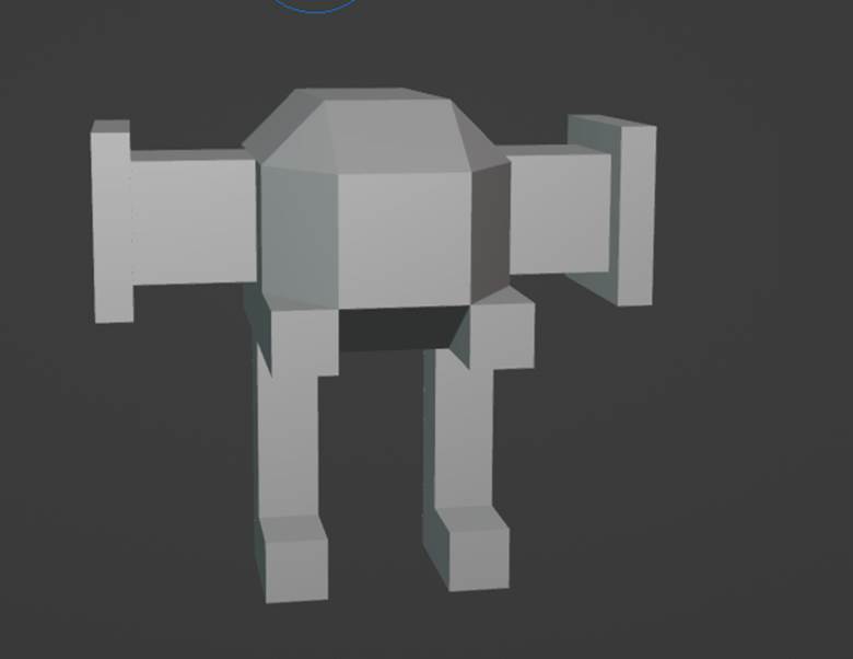
As you can see, our model now has 2 legs, which of course means it is a human person. Treat it well.
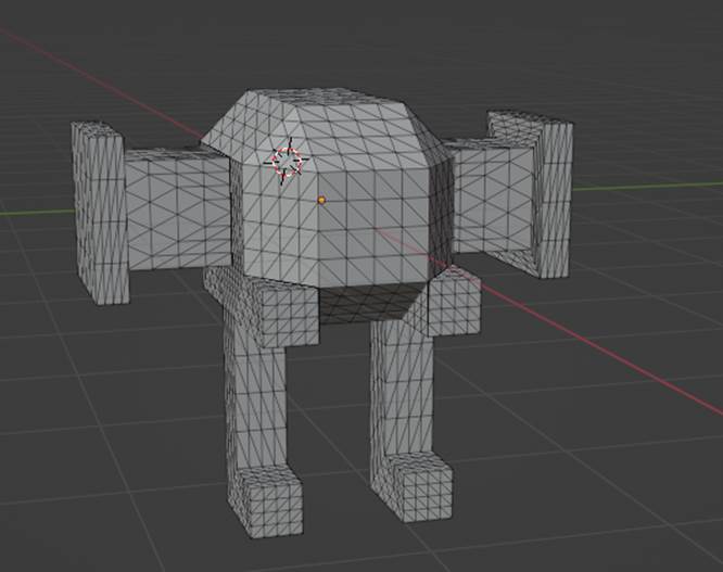
Now our next step will be sculpting, which of course will happen in the Sculpting mode, however, our model is not good for sculpting because it does not have enough polygons. Switch back to Modeling mode at the top of the screen and select the entire model again using A, then, press X to open the Delete menu. Click Limited Dissolve.
What Limited Dissolve has just done is removed all of the redundant faces from our model. This is a very useful tool, as over the course of making a model you may subdivide certain faces more or less than others and the model will be inconsistent, which is bad for sculpting. Now, we still want to have many polygons for sculpting, so with the entire model still selected, right click anywhere to open the Face Context Menu, use Triangulate faces, and then Subdivide twice. Our model now has a more uniform distribution of faces, as shown:
We are now ready to re-enter Sculpting mode.
I didn’t mention this when we previously entered sculpting mode, but you may have noticed that the GENUSAR™ has greatly expanded from modeling mode. The tools here are too many in number for me to explain them all while keeping this section concise (did you notice you can scroll through tools?), but most of them are definitely useful in one way or another, and I encourage you to play around with them to understand their function. Let’s go through some tools here.
Remember the Symmetry tab? Open it up again. This time, however, the object of interest is the Mirror option. If you want your sculpting to be symmetrical, make sure you select the relevant axis of symmetry.
Another important tab is the Brush Settings tab. It’s the second one in the Active Tool and Workspace Settings. Here you can set important attributes of your brush like if it has a positive or negative impact, its size, and its strength.
Let’s improve our model now; I’ll be mostly using the smooth tool as an example- again, feel free to use any of the sculpting tools if you feel it makes your model look better. Your model won’t be the exact same as mine anyways. When you have your tool and settings selected, simply drag your mouse over your model where you want the brush to apply.
The smooth tool looks like this, by the way:
![]()
You’d think it would have a less bumpy icon, eh?
After some sculpting, my model looks like this:
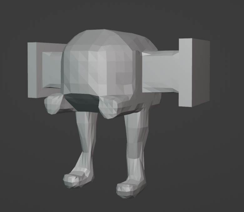
I hope the model you have made is even more iconic and breathtaking than mine.
The next step in perfecting this model should be the texturing, however, we should first check the face orientation. Blender displays the backsides of faces, but Unity does not, and if you accidentally make a face the wrong way and texture the model anyways, you will have to restart. This applies to any change you make to the model, actually, because of the way that texturing works: point is, make changes before you start texturing!
Anyways, to check for back faces, first click the arrow next to the Show Overlays button in the top right corner of the viewport:
![]()
After doing this, the Viewport Overlays drop down menu should open. In the Geometry section, check the box entitled Face Orientation. If you have done this correctly, your model should now look blue, like some sort of blue-coloured fruit.
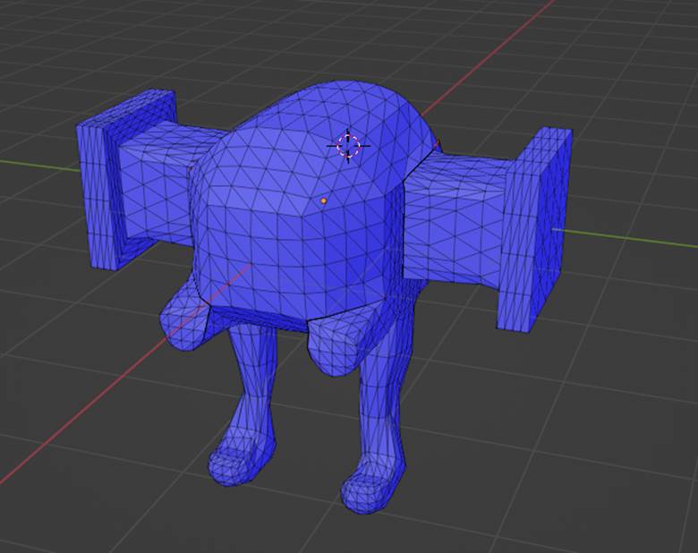
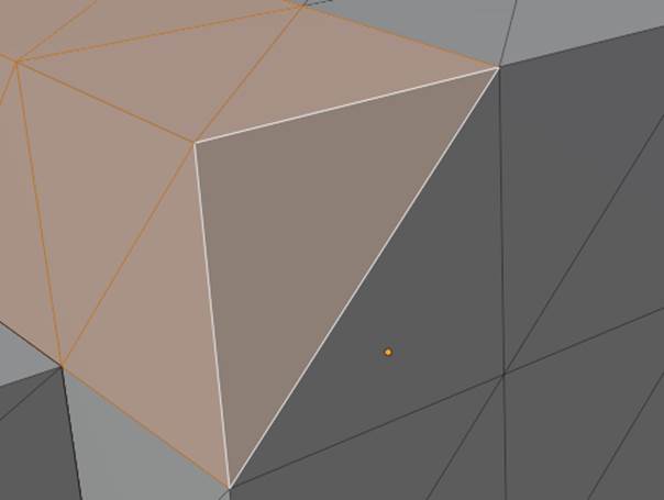
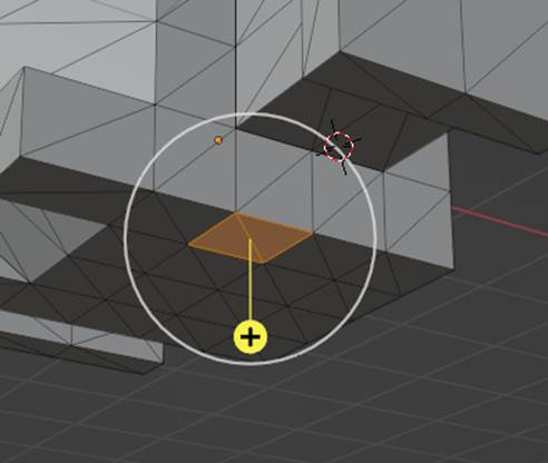
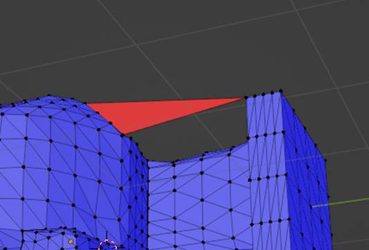
Now, if your model has any red (mine had a small amount on some edges), this means that a backface is visible on your model. There are two scenarios in which this is the case: holes in your model, or an inverted normal. Holes in your model can of course be fixed by constructing faces, but normals are a little more complicated. For this example, I’ve created a face on my model where the backface is visible on purpose. It appears red.
If I want to flip the normals so that this side is the one that will be the one visible in Unity, I will first have to select the face, open up the Mesh menu in the top left of the viewport, then the Normals sub-menu, and finally use Flip. Simple enough, right? And with superb geometric benefits!
Back to texturing, disable the Face Orientation option (or don’t, if you enjoy your model’s new watery hue) and select the entire model. Now, press U to open the UV Mapping menu and select Smart UV Project. This will open up a menu with options for projecting your model’s 3D mesh onto a flat surface so you can begin texturing. I recommend an angle limit between 50 and 60 degrees and an island margin of 0.005-0.01 to avoid problems with the texturing.
Now, with the model still selected, enter Texture Paint mode at the top of the screen. You should see the mesh of your model projected onto a flat surface on the left of the screen and your model in purple on the right of the screen.
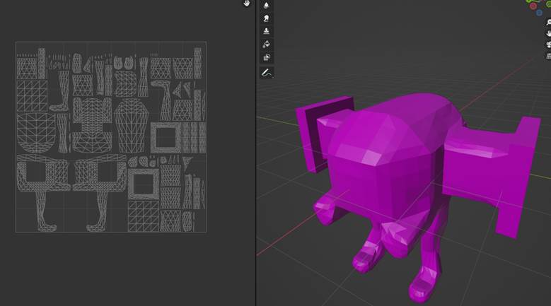
What the purple means is that your model has no texture. Alternatively, if you use colour theory, it means your model is luxurious and mysterious. How exciting!
Now, navigate to the Active Tool and Workspace settings on the right of the screen (wrench and screwdriver icon) and to the Texture Slots drop-down menu (should be right at the top). Now, press the + button and select Base Colour. This will open a menu entitled Add Paint Slot. The only options that concern us here are Name, which can be set to anything you want, and Color, which should be set to the color that you want most of your model to be using the wheel. Once both of these options are as desired, simply click OK. Your model should now have a colour that is not purple, unless of course you picked purple as a colour (mysterious). Now, you are ready to paint, but let me explain the Brush Settings for texturing mode first. There are actually 3 brush setting areas here, at the top of the Mesh editor, at the top of the Model editor, and in the Active Tool and Workspace settings. The latter has many more features, so we will be looking at it.
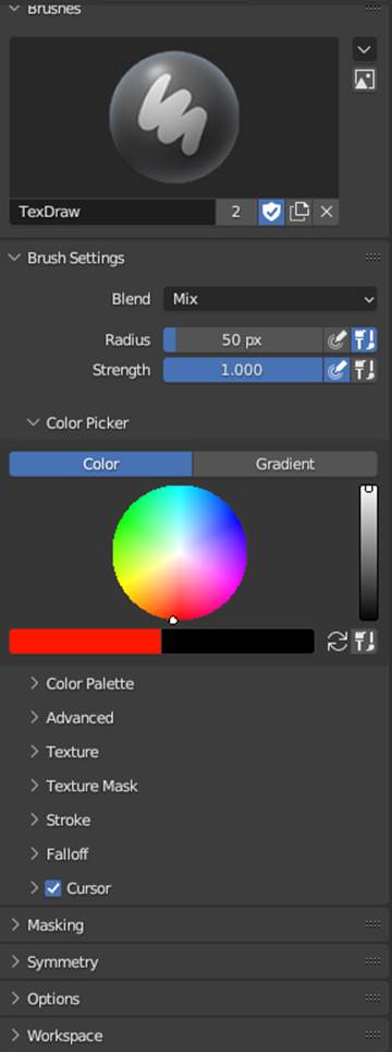
This is quite similar to the same settings tab in Sculpting mode, but it differs in many important ways too. Brush Settings let you change the size and strength of your brush, The Color Picker allows you to choose colours, Falloff allows you to change how blurry your brush is, and Symmetry allows you to choose between symmetrical and asymmetrical painting.
You can now paint on both the mesh side and the model side. Just make sure you have the mesh side set to the right file in the top center (should have the name that you made the base colour), and drag your brush around to make art… Get colouring!
Just as I intended. Very cool.
Now, before we leave, make sure to navigate to the top left of the mesh view where you will see an Image menu. Open this menu up and select Save As- make sure to put it in a location where you’ll find it later. Now, Save the model itself in the File menu at the top left of the screen- we’ll be importing this to Unity now.
First, let’s open Unity and create a new project with the 3D template named “Drip”. You’ve done this already, yes? Now, go to your system files and navigate to where your blender models are saved, then drag and drop your model into the Unity assets folder. Since we have a texture, you may also need to navigate to where your texture image is saved and drag that into Unity’s assets folder as well. In Unity, it should appear just as it did when you were painting it in Blender.
Now, drag the model into the Unity scene from the assets folder. If the texture was not applied onto the model automatically, drag it onto the model in the scene view.
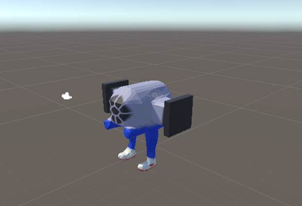
Amazing, right?
If you didn’t delete the Blender camera and light, they will make your object appear strange. If this is the case, right click on your model in the Hierarchy, click Prefab, then Unpack (prefabs cannot have their children deleted when packed) and delete the camera and light.
There’s one more thing to talk about now that we’re in Unity. When making complex 3D models that will collide with other objects a box collider may not suffice, with its boring cubic shape and lack of panache. Let’s select the model from the Hierarchy on the left of the screen. Now, hopefully you should remember from Mr. Killingbeck’s tutorials how to add components to an object in Unity, but if you don’t all you have to do is navigate to the Inspector on the right of the screen with our model selected and click Add Component at the bottom. In the menu that appears, search for Mesh Collider. When you select it, you should see a new Mesh Collider component in the inspector with a few options.
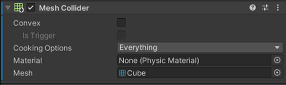
First, make sure to check the Convex box. We do this because this will be a player model: convex mesh colliders are able to collide with other mesh colliders such as maps. When making an actual Unity project, you may just want to use cylinder or box colliders for your player model to improve performance. That being said, mesh colliders for players can still be very useful, non-convex mesh colliders that do not collide with anything are used for checking if a player is hit in many shooter games. Anyways, click the ☉ symbol to the right of the Mesh option to bring up a menu of your models. You should select the model appearing as a textureless version of your model, if you don’t see any models like this, then the image for the model might not have loaded yet.
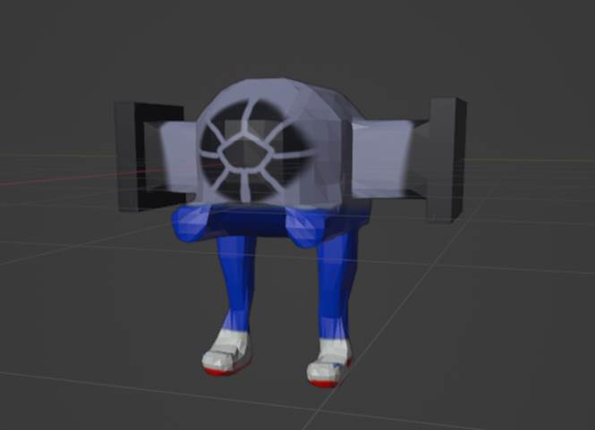
If this procedure has worked correctly, your model should now appear like this when selected:
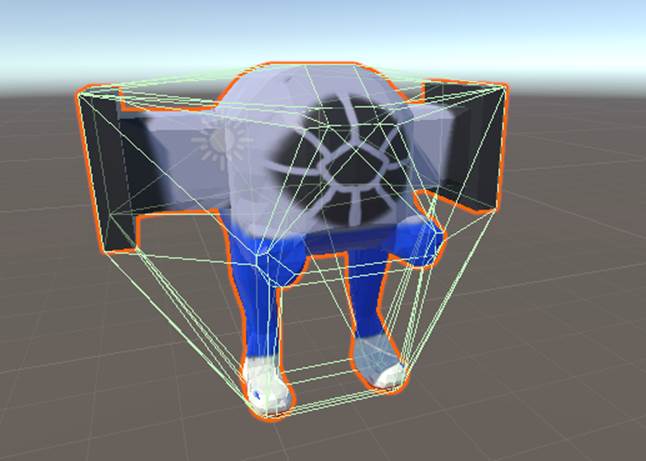
Very sci-fi, right? The lines just represent the hip new collision model that your rigidbody now has.
If your mesh collider has an improper rotation, an issue that is likely to happen to you at some point if you work with mesh colliders a significant amount, a quick fix is having the mesh collider component assigned to a very small or invisible cube that is a child of your main model. This will allow rotation of the collider independent from the main model.
If this worked for you alright, you can now make Unity games In style. If it didn’t, make sure to use your troubleshooting skills to their full extent by looking a bunch of different things up until you find an answer.
Good luck!